IMCE-02: Galvanized bolted split clamp-on fittings – Tee fitting ("T").

This installation is intended for cricket used by councils, schools, cricket clubs and associations. When selecting the actual final design and site location, install the cricket fencing, purchaser and installer should always consider local safety issues to restrict cricket balls from potentially causing injury to innocent bystanders, and or damage to nearby property.
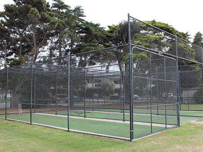
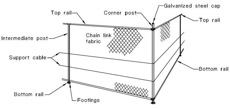
IMCE-01: Black coated cricket practice enclosure made by chain link fabric fencing.
requirement:
Cricket net fencing enclosures shall be installed truly to the alignment and finished level as directed by the project supervisor. The fence top shall evenly follow the same gradient as per cricket pitch base surface. The installation of the fence shall not include cutting or filling of the ground to achieve required finished levels unless other wise agreed between the purchaser and supplier. The rear fence should be set back 1400 mm behind the stump location.
Posts shall be equally spaced at 3000 mm maximum for both pipe rail cricket net fencing enclosures of flat roof and pitched roof. All of the fence post should stand vertically. Horizontal displacement shall not greater than the height of the post divided by 240.
Concrete post footings shall be not less than the minimum sizes specified in table 1 and table 2 following.
| Width range of gate leaf mm |
In-ground footings | Galvanized baseplates for concrete pavement | |||
|---|---|---|---|---|---|
| Minimum size of concrete footings (where applicable) | Baseplate option for bolting posts to concrete pavement mm |
Minimum size masonry anchors | |||
| Diameter mm |
Depth mm |
Diameter hole mm |
Depth mm |
||
| Up to 1200 | 250 | 750 | 150 × 150 × 8 4-hole |
12 | 75 |
| 1300-2400 | 300 | 1000 | 200 × 200 × 8 4-hole |
16 | 110 |
| 2500-3600 | 400 | 1100 | 300 × 300 × 10 4-hole |
20 | 125 |
| In-ground concrete footing sizes are designed for firm soil conditions. | Gate post with baseplates only when agreed between purchaser and supplier. To be installed with head clamped to top rail for additional support. | ||||
| Nominal height of chain link fabric mm |
Minimum size of concrete footings (where applicable) | Galvanized baseplates for concrete pavement | |||
|---|---|---|---|---|---|
| Baseplate option for bolting posts to concrete pavement mm |
Minimum size masonry anchors | ||||
| Diameter mm |
Depth mm |
Diameter hole mm |
Depth mm |
||
| 3000 or 3600 | 300 | 900 | 200 × 200 × 8 4-hole |
12 | 75 |
| 300 | 900 | 200 × 200 × 8 4-hole |
16 | 110 | |
| 250 | 750 | 150 × 150 × 8 4-hole |
12 | 75 | |
| Width range of gate leaf mm |
In-ground footings | Galvanized baseplates for concrete pavement | |||
|---|---|---|---|---|---|
| Minimum size of concrete footings (where applicable) | Baseplate option for bolting posts to concrete pavement mm |
Minimum size masonry anchors | |||
| Diameter mm |
Depth mm |
Diameter hole mm |
Depth mm |
||
| Up to 1200 | 250 | 750 | 150 × 150 × 8 4-hole |
12 | 75 |
| 1300-2400 | 300 | 1000 | 200 × 200 × 8 4-hole |
16 | 110 |
| 2500-3600 | 400 | 1100 | 300 × 300 × 10 4-hole |
20 | 125 |
| In-ground concrete footing sizes are designed for firm soil conditions | Gate post with baseplates only when agreed between purchaser and supplier. To be installed with head clamped to top rail for additional support. | ||||
| Nominal height of chain link fabric mm |
Minimum size of concrete footings (where applicable) | Galvanized baseplates for concrete pavement | |||
|---|---|---|---|---|---|
| Baseplate option for bolting posts to concrete pavement mm |
Minimum size masonry anchors | ||||
| Diameter mm |
Depth mm |
Diameter hole mm |
Depth mm |
||
| 3000 or 3600 | 300 | 900 | 150 × 150 × 8 4-hole |
12 | 75 |
| 300 | 900 | 200 × 200 × 8 4-hole |
16 | 110 | |
| 250 | 750 | 150 × 150 × 8 4-hole |
12 | 75 | |
| In-ground concrete footing sizes are designed for firm soil conditions. | Gate posts with baseplates only when agreed between purchaser and supplier. To be installed with head rail clamped to top rail for additional support. | ||||
| Refer to drawings for roof rail locations. | |||||
The constituents for footings shall be thoroughly mixed and the concrete placed in position and thoroughly compacted as soon as possible after mixing. This shall be done with due regard being taken of prevailing weather conditions at the time of placing, but in no case shall the time exceed 1 h after mixing.
After installation of posts and stays, the complete excavation shall be filled with concrete, and well compacted as filling proceeds (allowing 24 h for curing period).
If required by purchaser and installer, where suitable concrete pavement or similar surfaces exist, baseplate as show above may be in lieu of concrete footings as specified in table 1, 2, 3 and 4.
Pipe rails to roof areas shall be spaced to suit selvedge edge of fabric, allowing for some minimal overlap and intermediate support pipe rails shall not exceed 1500 mm spacing in either direction. Design options of cricket practice net fencing enclosure shows suitable examples of design layouts to assist in supporting roof fabric.
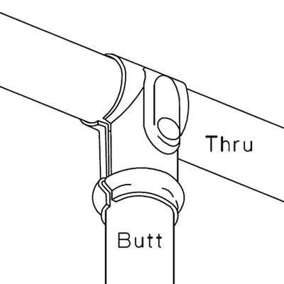
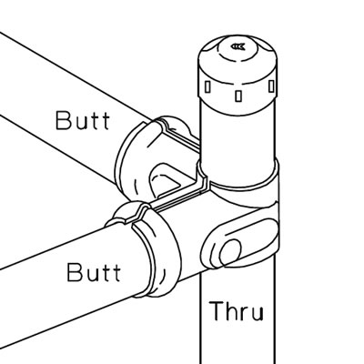
Pipe rails shall be securely connected to posts with galvanized bolted split clamp-on type fittings as shown below.
IMCE-02: Galvanized bolted split clamp-on fittings – Tee fitting ("T").
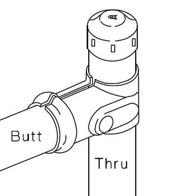
IMCE-03: Galvanized bolted split clamp-on fittings – Tee fitting ("T").
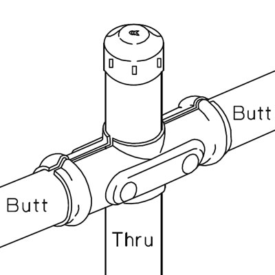
IMCE-04: Galvanized bolted split clamp-on fittings – Cross fitting ("X").
IMCE-05: Galvanized bolted split clamp-on fittings – Corner fitting ("C").
Ends of cable wires shall be firmly secured to all terminal posts. Each cable wire shall be wrapped around the terminal post twice with the end neatly cut off flush with cable wire. Cable wires shall be located to the inside face of posts facing cricket pitch. The cable shall be positioned to heights depending on fabric height selected: 2 mid cables set at 750 mm and 1500 mm from ground level for 3000 mm fabric or 3 mid cables set at 600 mm, 1200 mm and 1800 mm from ground level for 3600 mm fabric.
The cables shall be single strand 4 mm diameter wire helix spiraled with or without coating, or twin-strand 3.15 mm with or without coatings.
IMCE-06: This is the way of two cable wire installation for 3000 mm height fence.
Chain link fabric shall be placed on the inside of posts. For safety purposes, the chain link fabric shall be installed to both faces of all internal dividing fences. Strained taut between 1.0 and 1.2 kN and secured to each support cable, and all posts and mid-rails with tie wires, except at the end posts and gate posts.
At the end, corner and gate posts the chain link fabric shall be fully laced through each diamond to end posts, internal corner posts, gate posts and external pipe rails, where provided.
Fencing with top and bottom rail, the chain link fabric shall be fully laced through each diamond with 2.00 mm wire, to each rail at selvedge edge, or alternatively tied at each fourth diamond with double strand 1.57 mm wire, as selected by the purchaser. Each tie wire shall be twisted twice and the ends neatly cut off and bent over to avoid injury. Bottom rail should have maximum 30 mm clearance from finished ground levels.
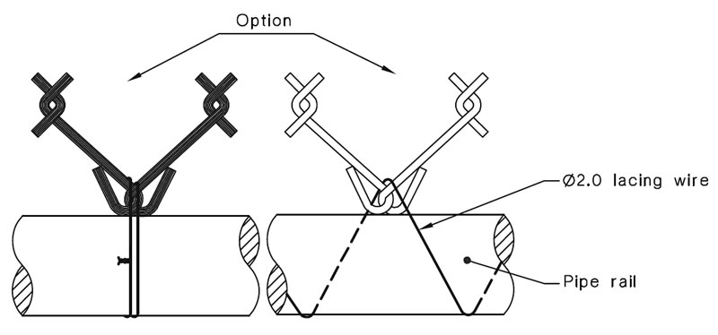
IMCE-07: Chain link fabric may be either tied or laced to the rails as shown above.
Barbed wire, only where required by the purchaser to protect roof area, shall be strained taut between 1.0 to 1.2 kN between posts and secured with tie wires to post indentations, and preset at 150 mm equal spacing above chain link fabric.
All galvanized threaded bolts and nuts used for attachment of fittings on fences and gates shall be sized correctly for clamp-on fittings and securely tightened with nuts fitted outside of the fence or as directed by the purchaser.
NOTE: Flush head sleeve nuts may be used if specified where potential injury may occur to players or spectators (eliminating bolt projection and nut).
Gates, where fitted, shall operate freely and fitted with shoot bolts. The clearance under the gates, when in the closed position, shall be 30 mm maximum to clear the surface.
Unless otherwise specified by the purchaser, excavations of soil from postholes shall be spread neatly outside the fence line, (away from cricket pitch surface). Any rock excavated and surplus debris from post holes shall be removed from site.
For your conveniently accessible to crickets' chain link fabric net fencing, gate, pipe and design options, please refer to the following articles:
Note:
All of our cricket are designed according to the standard AS 1725.4.
